- DMVPN stands for Dynamic Multipoint Virtual Private Network.
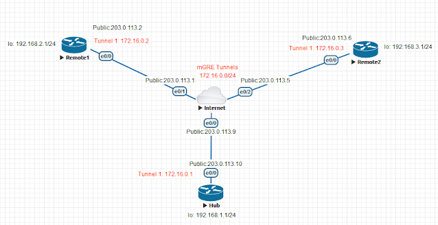
- DMVPN is used to create a hub-and-spoke VPN architecture.
- DMVPN Phase 1 provides hub-and-spoke communication. Spoke-to-spoke communication will always traverse the hub router.
- DMPVN Phase 2 supports dynamic spoke-to-spoke tunnels (appropriate routing configuration required).
DMVPN Components:
- mGRE - Multipoint GRE eliminates the need for numerous point-to-point GRE tunnels.
- NHRP - Next Hop Resolution Protocol, used for mapping the WAN IP address to the GRE tunnel IP address.
- IPSec - IP Security, used for securing TCP/IP traffic. IPSec is optional but recommended.
Each spoke registers its public IP address with the hub and queries the NHRP database for the public IP address of the destination spoke it needs to build a VPN tunnel.
mGRE Tunnel Interface is used to allow a single GRE interface to support multiple IPSec tunnels and helps dramatically to simplify the complexity and size of the configuration.
A GRE interface definition includes:
interface Tunnel 0
A mGRE interface definition includes:
interface Tunnel 0
It is important to note that mGRE interfaces do not have a tunnel destination. Because mGRE tunnels do not have a tunnel destination defined, they cannot be used alone. NHRP fills this gap by telling mGRE where to send the packets.
DMVPN OPERATION - HOW DMVPN OPERATES
Before diving into the configuration of our routers, we’ll briefly explain how the DMVPN is expected to work. This will help in understanding how DMVPN operates in a network:
- Each spoke has a permanent IPSec tunnel to the hub but not to the other spokes within the network.
- Each spoke registers as a client of the NHRP server. The Hub router undertakes the role of the NHRP server.
- When a spoke needs to send a packet to a destination (private) subnet on another spoke, it queries the NHRP server for the real (outside) address of the destination (target) spoke.
- After the originating spoke learns the peer address of the target spoke, it can initiate a dynamic IPSec tunnel to the target spoke.
- The spoke-to-spoke tunnel is built over the multipoint GRE (mGRE) interface.
- The spoke-to-spoke links are established on demand whenever there is traffic between the spokes. Thereafter, packets are able to bypass the hub and use the spoke-to-spoke tunnel.
- All data traversing the GRE tunnel is encrypted using IPSecurity (optional)
FOUR STEPS TO FULLY CONFIGURE CISCO DMVPN
To help simplify the configuration of DMVPN we’ve split the process into 4 easy-to-follow steps. Each step is required to be completed before moving to the next one. These steps are:
- Configure the DMVPN Hub
- Configure the DMVPN Spoke(s)
- Protect the mGRE tunnels with IPSecurity (optional)
- Configure Routing Between DMVPN mGRE Tunnels (static routing or routing protocol)
CONFIGURING THE DMVPN HUB ROUTER
nterface Tunnel0
Engineers familiar with GRE Tunnels will immediately notice the absence of the tunnel destination command. It has been replaced with the tunnel mode gre multipointcommand, which designates this tunnel as a multipoint GRE tunnel.
The ip nhrp map multicast dynamic command enables the forwarding of multicast traffic across the tunnel to dynamic spokes. This is usually required by routing protocols such as OSPF and EIGRP. In most cases, DMVPN is accompanied by a routing protocol to send and receive dynamic updates about the private networks.
The ip nhrp network-id 1 command is used to identify this DMVPN cloud. All routers participating in this DMVPN cloud must have the same network-id configured in order for tunnels to form between them.
The ip nhrp authentication command is used to allow the authenticated updates and queries to the NHRP Database, ensuring unwanted queries are not provided with any information about the DMVPN network.
CONFIGURING THE DMVPN SPOKES ROUTERS
After a couple of seconds, we receive confirmation that our tunnel interface is up:
*May 11 18:20:39.917: %LINEPROTO-5-UPDOWN: Line protocol on Interface Tunnel0, changed state to up
The ip nhrp nhs 172.16.0.1 command tells our spoke router who the Next Hop Server (NHS) is, while the ip nhrp map 172.16.0.1 203.0.113.10 command maps the NHS address (172.16.0.1) to the Hub’s (R1) public IP address (203.0.113.10).
The ip nhrp map multicast 203.0.113.10 ensures multicast traffic is sent only from spokes to the hub and not from spoke to spoke. All multicast traffic should be received by the hub, processed and then updates are sent out to the spokes.
Lastly, notice that tunnel source FastEthernet0/1 command. All spokes with dynamic WAN IP address must be configured to bind the physical WAN interface as the tunnel source. This way, when the spoke’s WAN IP changes, it will be able to update the NHS server with its new WAN IP address.
VERIFYING DMVPN FUNCTIONALITY AT THE R1 HUB ROUTER
The first column #Ent shows the number of entries that exist in the NHRP Database for the same spoke. Usually, we wouldn’t expect to see more than one for each spoke.
The second column Peer NBMA Addr presents the spoke’s public IP address, while the third column, Peer Tunnel Add, shows each spoke’s local Tunnel’s IP address.
Next, the State column shows the current state the tunnel is in. In our case, both tunnels are UP. Right next to the State is the UpDN Tm, which is the Up or Down Time of the current State. This is a very important bit of information as you can clearly see out how long your tunnel has been in its current state.
Lastly, the Attrib column shows the type of tunnels established by the spokes. D stands for Dynamic, S for Static and I for Incomplete. Usually dynamic spokes will create D type tunnels. Tunnels established from the spokes to the Hub router are expected to be S type, since the Hub remains static.
VERIFYING DMVPN FUNCTIONALITY AT THE R2 & R3 SPOKE ROUTER
ROTECTING - ENCRYPTING DMVPN MGRE TUNNELS WITH IPSEC
VERIFYING THE DMVPN CRYPTO TUNNELS
ROUTING BETWEEN DMVPN MGRE TUNNELS
http://www.firewall.cx/cisco-technical-knowledgebase/cisco-services-tech/896-cisco-dmvpn-intro.html
http://www.firewall.cx/cisco-technical-knowledgebase/cisco-routers/901-cisco-router-dmvpn-configuration.html
Comments
Post a Comment