Configure Packet Captures on AireOS WLC
https://www.cisco.com/c/en/us/support/docs/wireless-mobility/wireless-lan-wlan/211342-packet-captures-on-aireos-wlc.html
A distribution system port connects the controller to a neighbor switch and serves as the data path between these two devices.
The service port is controlled by the service-port interface and is reserved for out-of-band management of the controller and system recovery and maintenance in the event of a network failure. Use of the service port is optional.
An interface is a logical entity on the controller.


Ports and Interfaces
A port is a physical entity, two types of ports: distribution system ports and a service port.
12
|
|||
A distribution system port connects the controller to a neighbor switch and serves as the data path between these two devices.
The service port is controlled by the service-port interface and is reserved for out-of-band management of the controller and system recovery and maintenance in the event of a network failure. Use of the service port is optional.
An interface is a logical entity on the controller.
- Management interface (static and configured at setup time; mandatory)
- AP-manager interface (static and configured at setup time; mandatory)
- Virtual interface (static and configured at setup time; mandatory)
- Service-port interface (static and configured at setup time; optional)
- Dynamic interface (user-defined)
The management interface is the default
interface for in-band management of the controller and connectivity to
enterprise services such as AAA servers. It is also used for
communications between the controller and access points
For CAPWAP, the controller requires one management interface to control
all inter-controller communications and one AP-manager interface to
control all controller-to-access point communications,
A controller has one or more AP-manager
interfaces, which are used for all Layer 3 communications between the
controller and lightweight access points after the access points have
joined the controller. The AP-manager IP address is used as the tunnel
source for CAPWAP packets from the controller to the access point and as
the destination for CAPWAP packets from the access point to the
controller.
The virtual interface is used to support
mobility management, Dynamic Host Configuration Protocol (DHCP) relay,
and embedded Layer 3 security such as guest web authentication and VPN
termination. It also maintains the DNS gateway host name used by Layer 3
security and mobility managers to verify the source of certificates
when Layer 3 web authorization is enabled.
Dynamic interfaces, also known as VLAN interfaces, are created by users and designed to be analogous to VLANs for wireless LAN clients

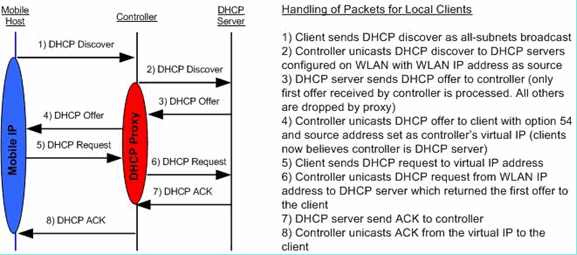
DHCP proxy mode - DHCP helper function
DHCP bridging mode - Transparent in DHCP Transaction.
https://www.cisco.com/c/en/us/support/docs/wireless/4400-series-wireless-lan-controllers/110865-dhcp-wlc.html
==================
Virtual WLC
optional access port for the Service Port - vNIC1
trunk for Dataport - vNIC2
===========================
(Cisco Controller) >show debug
MAC Addr 1.................................. 4A:C3:B5:7B:21:FA
Flex-AP Client Debugging ................... disabled
Flex-Group Client Debugging ................ disabled
Debug Flags Enabled:
(Cisco Controller) >
(Cisco Controller) >
(Cisco Controller) >debug mobility handoff enable
(Cisco Controller) >
(Cisco Controller) >show debug
MAC Addr 1.................................. 4A:C3:B5:7B:21:FA
Flex-AP Client Debugging ................... disabled
Flex-Group Client Debugging ................ disabled
Debug Flags Enabled:
dhcp packet enabled.
Client Event enabled.
dot11 mobile enabled.
dot11 state enabled
dot1x events enabled.
dot1x states enabled.
mobility global handoff enabled.
mobility client handoff enabled.
pem events enabled.
pem state enabled.
802.11r event debug enabled.
802.11w event debug enabled.
CCKM client debug enabled.
(Cisco Controller) >
(Cisco Controller) >
(Cisco Controller) >debug client ?
<MAC addr1> Enter MAC address
(Cisco Controller) >debug client 4A:C3:B5:7B:21:FA
=====
https://community.cisco.com/t5/security-knowledge-base/top-six-important-cisco-wlc-settings-for-ise-integration/ta-p/3643795
Comments
Post a Comment